Coordinate and reference frame format
- 3D Mode" method :
By default, the global reference frame of the 3D model is used.
To select a new origin, we can select either a point, a vertex, a circle or an arc. The axes of this new reference frame correspond to the model's global reference frame. The point is selectable in all views. If a circle or arc is selected, the center point is taken into account for this origin.
You need  the selection to continue.
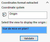
If we leave the default selection on "Origin"the tool GetCoordinates2D to select the drawing view to be taken into account, then confirm.
 The question doesn't arise if we select an entity that already belongs to a view.
When the origin is validated, a first line is created in the table, with any comments entered and the first annotation (depending on the setting in the table template). The XYZ coordinates displayed are 0,0,0.
It is possible to change marker after starting extraction  or after validating the table by simply editing the MacroFeature. All coordinates are recalculated. If you select an entity that has already been marked, the new marker "1" replaces the old marker. The old marker disappears, as does the line in the table. The numbering of subsequent markers is not recalculated.
- Projected mode" method :
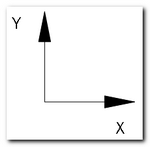
- The XY coordinate system is always parallel to the sheet (X horizontal and Y vertical).
- The default origin is the projection of the 3D model origin in the selected view.
- You must select the origin and validate the selection to continue.
- A new origin can be selected: a point, a vertex, a circle or an arc (the center is taken into account).
- When the user selects the origin in a view, the point selection view is automatically taken into account.
- When the user changes the origin, he cannot select one in another view.
- A preview of the XY marker (sketch block) is constantly displayed in the selected view.
This sketch block Origin.sldblk"is saved in the :
"C:\UsersUserNameAppDataLocalAxemblemyCADtools 2015GetCoordinates2D\Blocks".
 This block is automatically generated in the above installation directory, and cannot be customized..
- When the origin is validated, a first line is created in the table with any comments entered, as well as the first annotation. The X,Y coordinates displayed are 0,0. If the table template includes a column for Z coordinates, this value will be zero. It is possible to change the coordinate system after extraction has begun
 or after validating the table by simply editing the MacroFeature. All coordinates are recalculated. If an entity already marked is selected, the new marker "1" replaces the old marker. The old marker disappears, as does the line in the table. The numbering of subsequent markers is not recalculated. The sketch block representing the marker is moved to the newly selected entity.
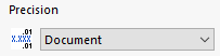
The format of the annotations is defined in the SOLIDWORKS document options, however in this area it is possible to specify :
- Coordinate accuracy.
 -->
--> 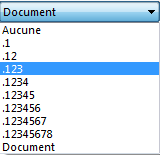
- As well as managing the display of zeros on the right.