Generating points on a series of surfaces by grid repetition
This type of selection generates a series of points from a grid oriented in two directions, which are then projected onto the selected surfaces. These points are created in a 3D sketch. arrows (blue and red) are only visible if a starting point is selected.
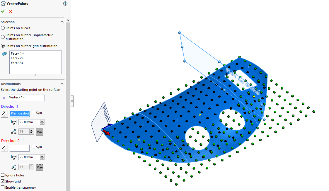
The principle is to select a series of surfaces, and/or faces, and a vertex to define a starting point.
Then simply select a plane or flat face for the ''.Direction 1''. The selection of the ''Direction 2is not mandatory.
- If the ''Direction 2If '' is not selected, the tool automatically sets the direction perpendicular to ''.Direction 1''.
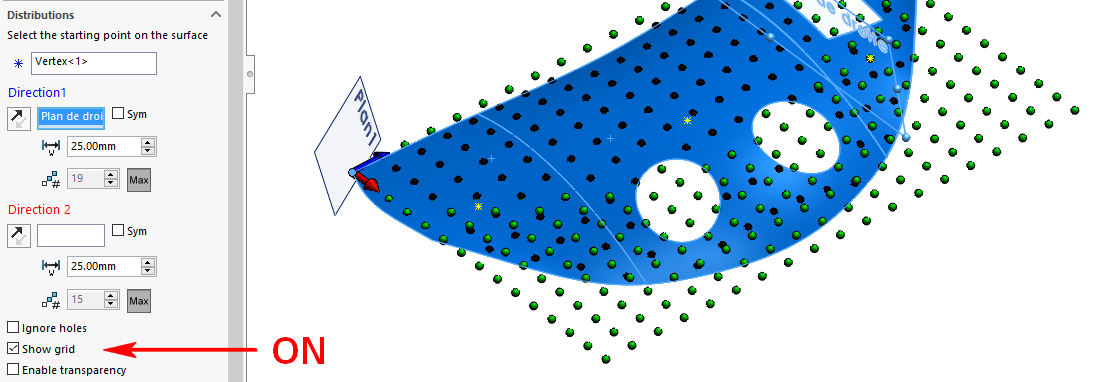
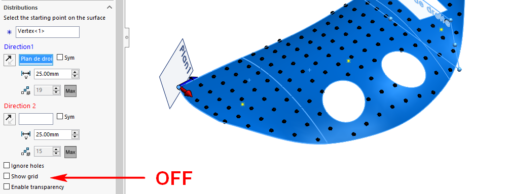
This creates a grid. It can be displayed graphically by checking the option  . The color of this grid is set to '' by default.Green''.
Points (color Black) are projected onto the selected surfaces.
 Only points where surfaces meet are retained.
If the preview result is not what you want, you can click on the  to reverse the direction or click on
  to see which sides the grid is generated from.
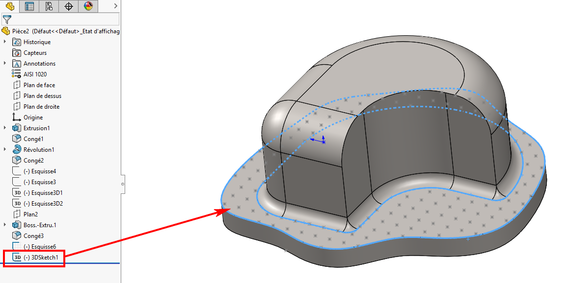
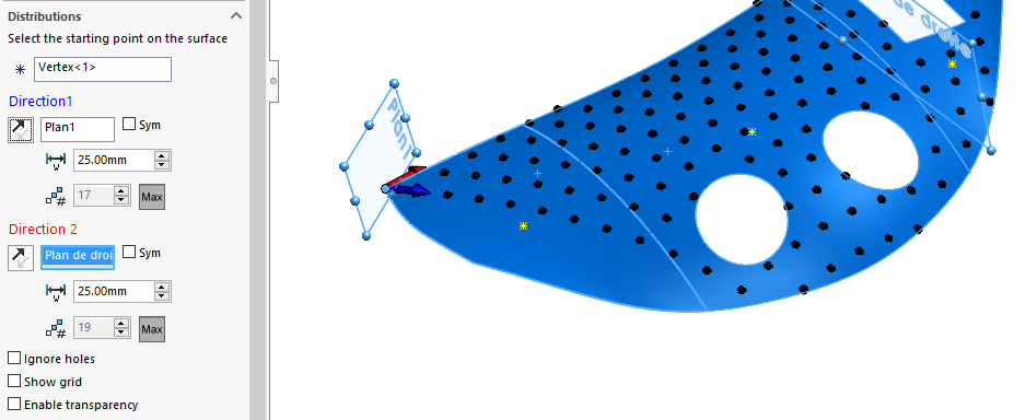
- To define a ''Direction 2Simply select a plane or plane face. A red arrow is positioned on the selected vertex to show the direction, you can click on the icon to reverse it.
Example : ''Direction 1'' --> ''Plan1'' and ''Direction 2'' --> ''Plan de droite''.
- ''Ignore drilling'' :
Selected faces may contain "holes" (of any shape). By checking this option, the tool will ignore the boundaries of these holes, creating points on the missing faces.
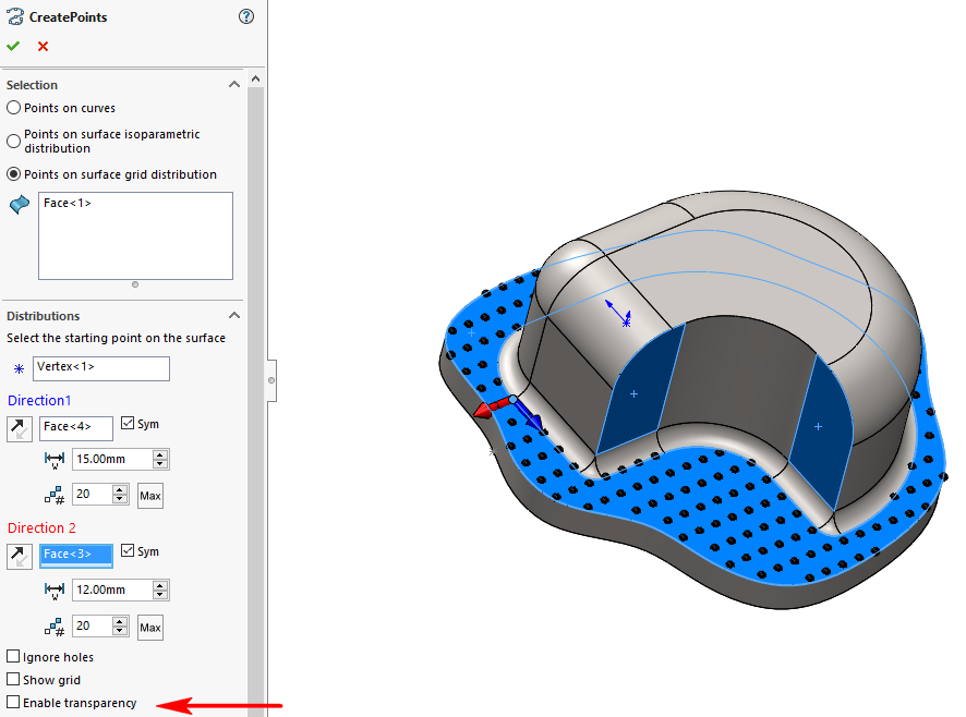
- ''Enable transparency'' :
In the context of a part comprising only surface elements, this option has no real influence on the graphics.
This is not the case when we're working in the context of a part with volumetric bodies that may obscure part of the preview.
 Only points where surfaces meet are retained.
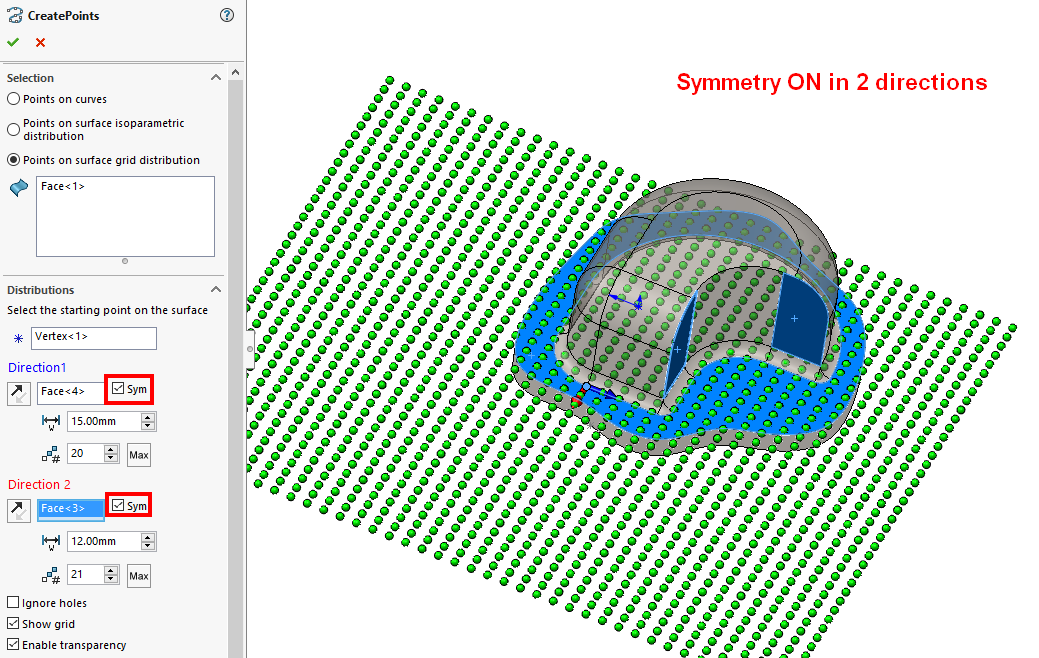
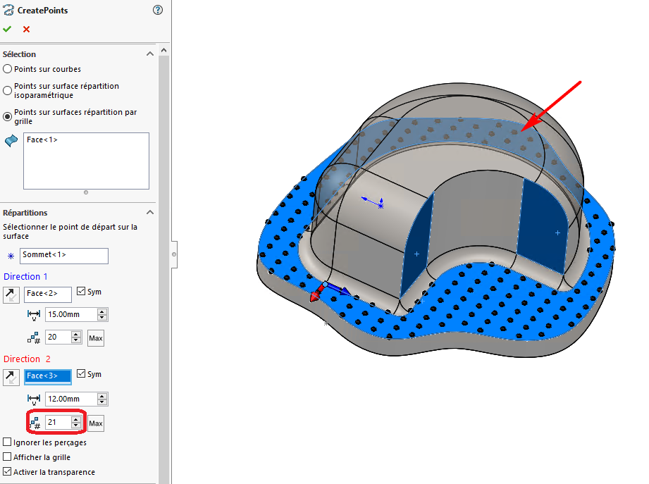
Example Two selected flat faces define the two directions, a pitch and a number of points are specified, and symmetry has been requested in both directions to cover the entire surface.
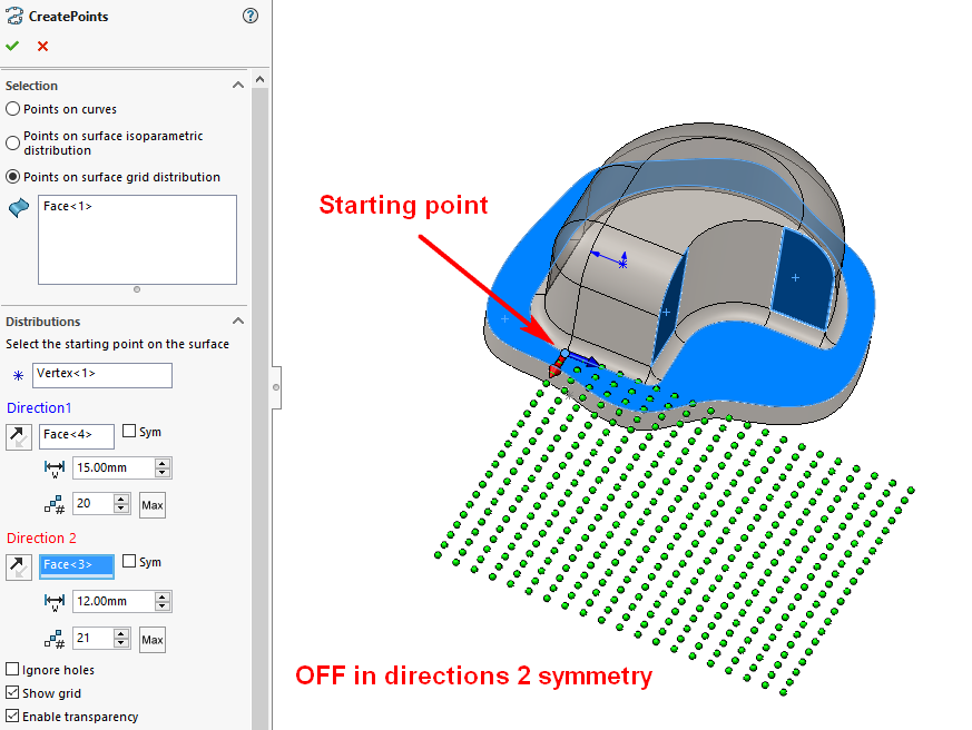
- If this option is unchecked, only points on the periphery of the selected face are visible:
- When checked. Checking this option puts the part in transparent mode, allowing all points to be seen:
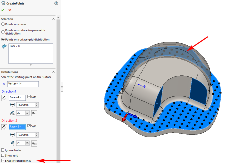
We can thus see that according to the ''Direction 2We need more stitches to cover the whole face. So we're going to increase the number  to 21 to correct this.
- As points are created from the starting point (belonging to the face) and in both directions, the result may not cover all selected faces.
To remedy this situation, you can either :
- Click on the
 so you don't have to enter the number of points.
 - Choose another starting point.
- Change pitch
 .
. - Enable the creation of points symmetrically to each direction by checking the option
 .
.