Results" zone
This zone is common to all three types of point generation (on a series of curves, on a surface by distribution, on a series of grid surfaces).
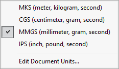
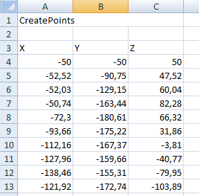
Coordinates are exported in the units and decimal places defined in the part document options.
By default, the coordinates of created points are taken relative to the workpiece origin. You can select a coordinate system, a sketch point or a vertex, and the coordinates will be calculated relative to this point.
 This point cannot be the same as the starting point. If this is the case, you need to create a
 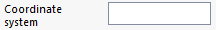 on this point (or vertex) and select it.
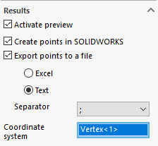
- ''Activate previewBy checking this option, for each change and validation of information, you can instantly preview the result in the graphical window.
However, there are two default limits for this preview:
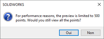
- Up to 500 points generated, the preview is displayed correctly, beyond which a validation window asks the user for authorization to display the points or not.
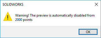
- Above 2000 points, for performance reasons, a message indicates that preview is automatically disabled.
You can, however, continue to modify values (blind). When you validate the parameters, the points are calculated and created.
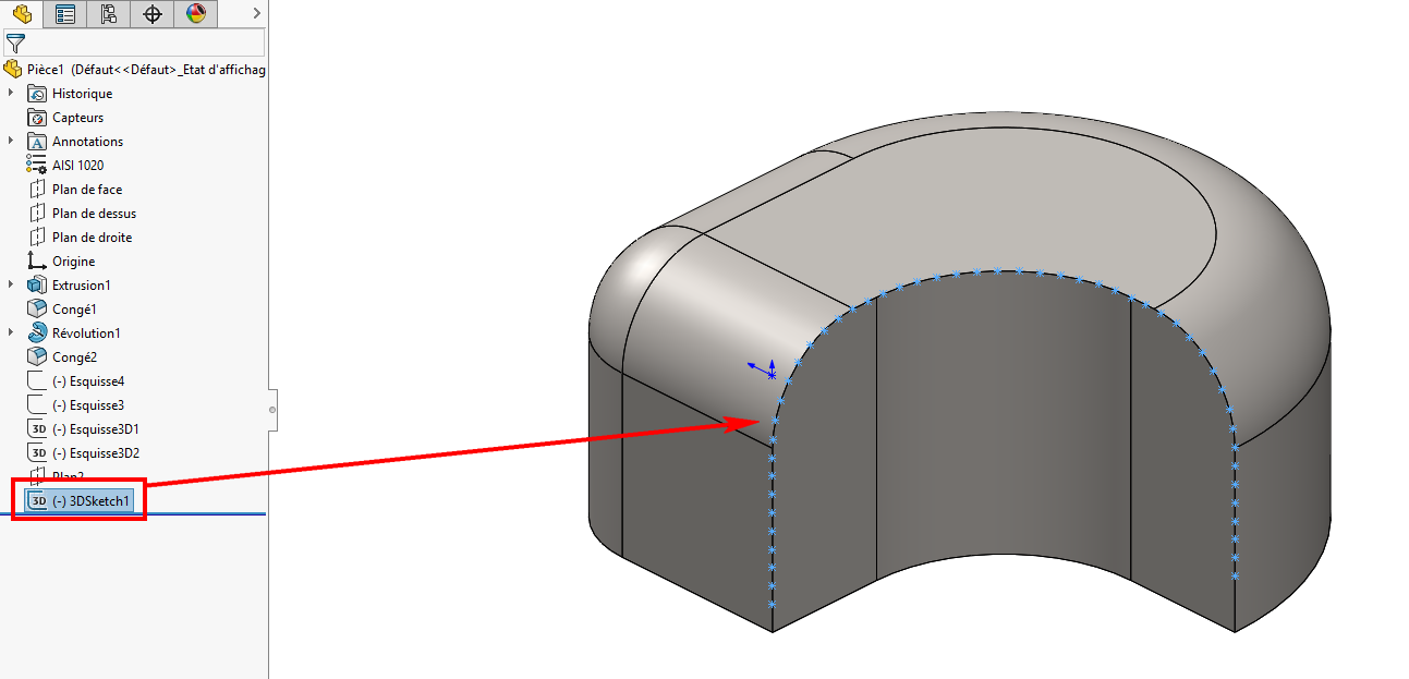
- ''Creating points in SOLIDWORKS'' - this option is usually checked and will generate a 2D sketch or a 3D sketch depending on the geometry and parameters selected. For example, this option will be unchecked if only export to a file is required.
If this option is unchecked, only the file will be generated. This can be very useful if you want to generate hundreds or even thousands of points. In this case, SOLIDWORKS performance will not be good, and it will still be possible to re-read the point file with ScanTo3D.
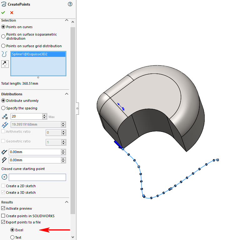
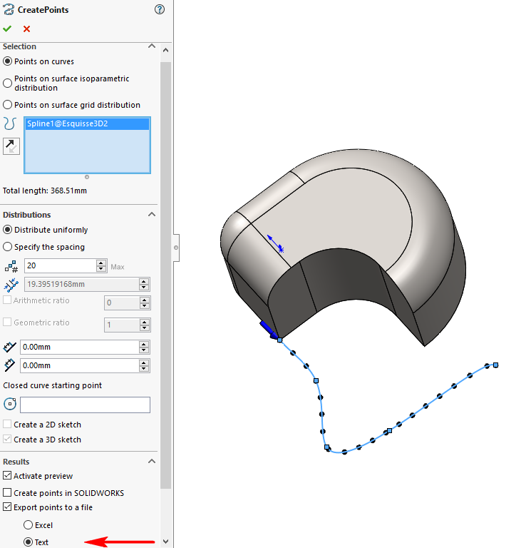
- ''Export points to a fileBy checking this option, you can export the calculated points to a :
- Type Excel''. Then simply save the file, giving it a name and location.
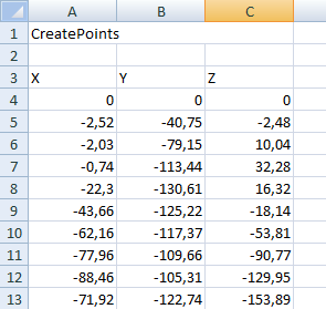
Example - Export to an Excel file to create 20 points on a 3D curve relative to the global reference frame.
By clicking on the  reverses the direction (start or end) of point generation on selected entities
  .
.
- Type "Text". When exporting to a text file, you can select the separator character from the list. The choice is between ",", ";"or "Tabulation". Then simply save the file, giving it a name and location.
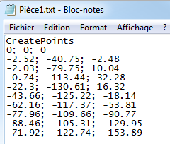
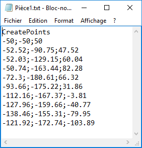
Example - Export to a text file to create 20 points on a 3D curve relative to the global reference frame.
By clicking on the reverses the direction (start or end) of point generation on selected entities .
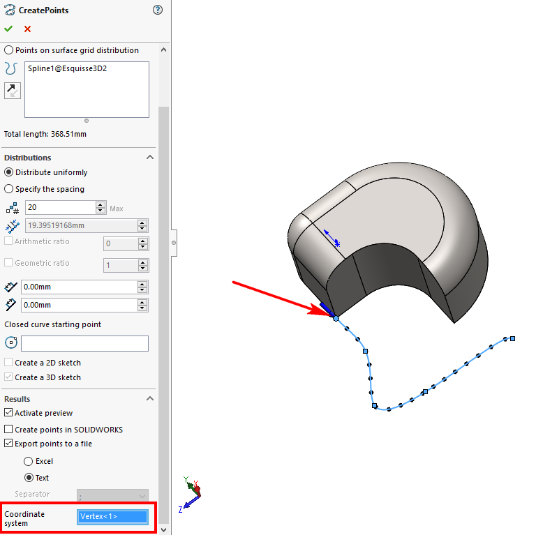
- ''Coordinate system'' :
By default, the coordinates of generated points are calculated in relation to the part's global reference frame (origin). It is possible to select an entity to modify this coordinate system. The elements that can be selected are :
- A 2D or 3D point on a sketch.
- The end of a 2D or 3D sketch entity.
- A summit.
- A previously created coordinate system.
Example - Export to an Excel file to create 20 points on a 3D curve by selecting, as the new coordinate system, the 3D vertex coincident with the 1st point of the curve. The new coordinate system retains the same orientation (X, Y, Z) as the global coordinate system.
By clicking on the reverses the direction (start or end) of point generation on selected entities .
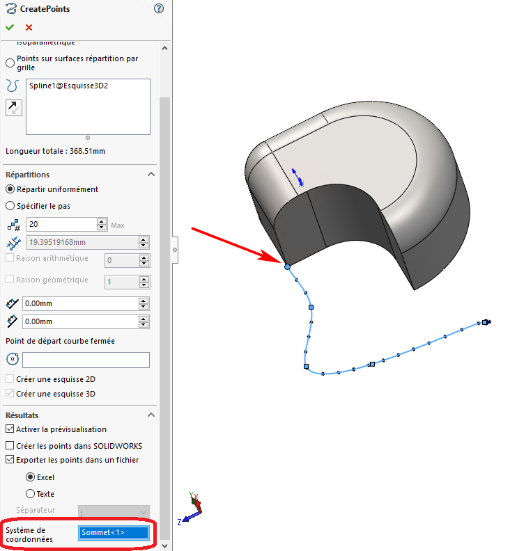
Example - Export to a text file to create 20 points on a 3D curve by selecting the 3D vertex coincident with the 1st point of the curve as the new coordinate system. The new coordinate system retains the same orientation (X, Y, Z) as the global coordinate system.
By clicking on the reverses the direction (start or end) of point generation on selected entities .