
Overview
For example, based on the changes in the positions of the two cylinders, we want to calculate the angle and the maximum distance that the wheel's center point must travel. We can visualize this path by creating a 3D path.
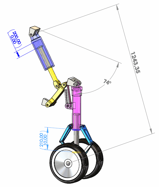
 Attention : when the 3D model evolves, there is no automatic update of the geometries generated by the tool. To update the information, simply relaunch the tool.
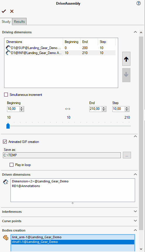
First, we need to consider the context of an assembly in which the positioning of certain components is controlled by dimensions. This allows us to vary these dimensions within a given range (start-end) in specific increments.
In this window, you'll find the information you need to specify to define the process:
- Add the control dimensions to be adjusted.
- Selection of controlled dimensions to extract the processing results.
- (Optional) Selection of points to generate 3D curves.
- The possible creation of bodies.
- Selection of objects to test for possible interference.
- Viewing the results.