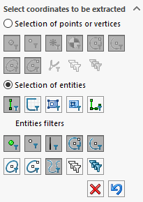
Entity selection and filters
All filters can be checked  or unchecked
  in a single action.
 Clicking on this icon deletes all rows generated in the table and their associated markers. Numbering restarts at the start value.
 Clicking on this icon cancels the last selection. The associated table line and marker are deleted. Numbering restarts at the previous value.
In this section, there are 2 concepts to consider: selection type and selection filters.
- Entity selection :
Only one selection can be activated. To restrict the choice of selections, you can activate one or more entity filters.
 (individual entity filter) This icon is used to select only individual entities (linear or circular edges, sketch entities, etc.).
 This icon is used to select sketch entities only. Use the same rules as described above.
 This icon is used to select faces and extract the coordinates of entities (edges) external to the face.
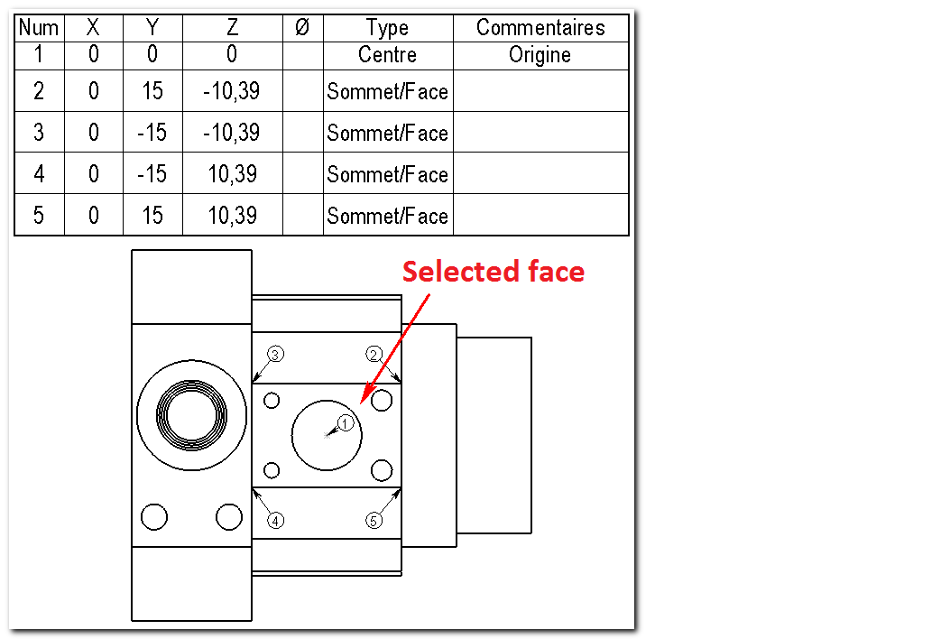
Example :
In the image below, by selecting the flat face, we extract the coordinates of the edges of the outer edge of this face.
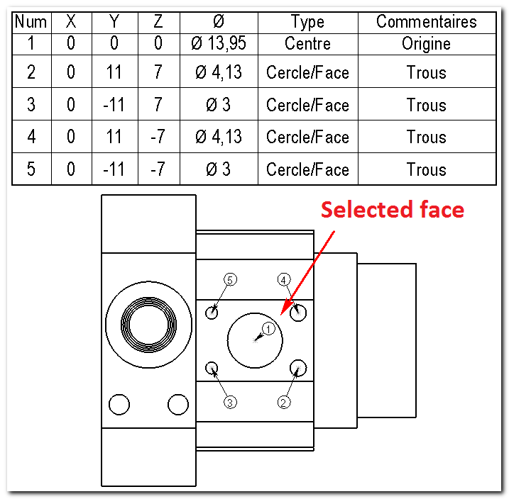
 This icon allows you to select faces and extract the coordinates of entities (edges) internal to that face.
Example :
In the image below, by selecting the plane face, we extract the coordinates of all the holes located inside this face, except for the circle in the center, which has been taken as the origin.
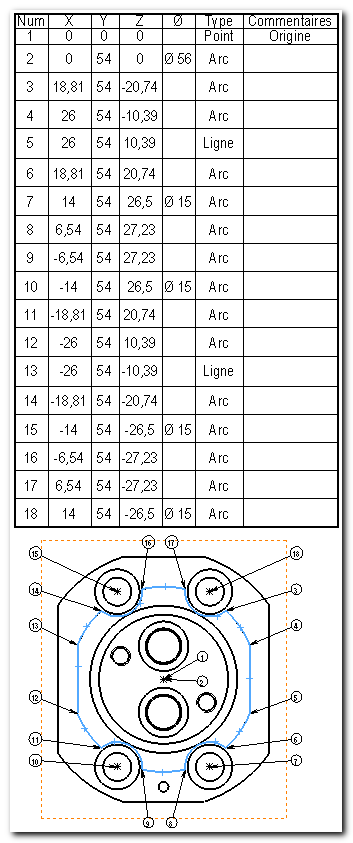
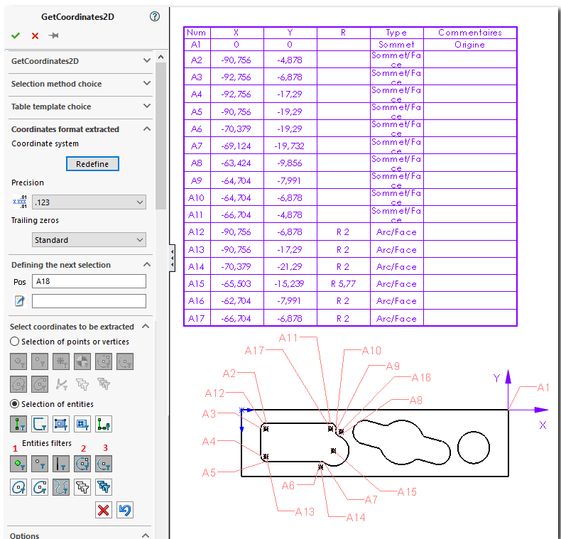
 This icon is used to select a succession of entities adjacent. Contiguity analysis is performed between the selected entity and the previous entity only. It's up to the user to select his chaining in the right order, in the right direction, and to choose his first entity carefully. A message is sent to the user if the selected entity is not contiguous with the previous one. It is the selection of the second entity that defines the starting point and order of chaining.
The X,Y,Z (in 3D mode) or X,Y (in projected mode) coordinates of the vertices are extracted, once only, in the order of chaining. When a circular or elliptical arc is encountered, the Xc,Yc,Zc coordinates of the center, the R value of the radius (or D of the diameter) for circular arcs and the extremities are extracted.
If the chain is closed, the last vertex (which is actually the first) is not processed. In the case of an arc, the order in which points are extracted is as follows: First point, Center, Second point.
Example :
In the image below, by selecting all the chained edges, we've extracted the coordinates of all the ends as well as the center and diameter points of the circular edges.
 For these last 2 filters and the order of annotations will follow the order of checked entity filters.
Example :
In the image below, by selecting the inner face of the pocket, the coordinates are extracted in the order of the filters: ''1'' summits, then ''2'' circles then ''3circular arcs. If you want the annotations to follow each other, use the (Entity string filter) and manually select entities in the desired order.
- Entity filters :
For points  summits
  circle centers
  etc ... we extract the coordinates XY of the point and Xc, Yc of the center point.
For linear lines and edges  we extract X1, Y1, X2, Y2 from the 2 end points.
For circular arcs  or ellipse portions
  we extract X1, Y1, X2, Y2 from the 2 end points, as well as the value R of the radius (or D of the diameter) and the center point Xc, Yc for the arcs.
For splines  we extract the coordinates of the 2 ends and all the points of the spline. If the spline is closed, the end points are merged.
In 3D mode, the Z coordinate is added.
- If you wish to retrieve the coordinates of the ends of arcs of circles (sketches or edges), you must activate the ''.Entity selection'' AND uncheck
 option