The scales

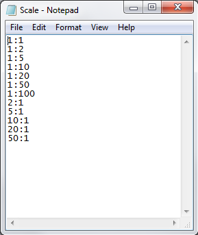
When creating component views, the AssemblyBoard calculates the possible scale to fit the view into the boxes defined in the pages. The tool then takes the smallest scale specified in the scale file that can fit in the view. This file can be customized according to the most commonly used scales for this job. These are not the scales offered in SOLIDWORKS drawing views.
Example of a custom scale file :
By clicking on the  A custom scale file can be used. This path can point to a network drive and is saved when this search icon is clicked again.
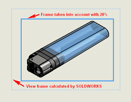
In some cases the "Bounding Box" around the view calculated by SOLIDWORKS is a little large, which means that a scale has to be taken by AssemblyBoard smaller. It is then possible to give a "Authorized increase factor for view scale" allowing a more appropriate scale. For example, it will be possible to switch to a 5:1 scale instead of the 4:1 used initially. Obviously, if in the scale file I've only defined an interval from 1:1 to 5:1, the choice will be quite limited!
 Scales are not chosen at random, which is why it's important to define your scale file carefully.
Example by setting to 20%.