
Export options
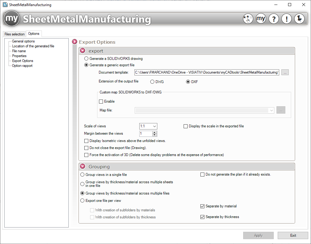
- Export:
- " Generate a SOLIDWORKS drawing ":
By checking this option, you can select a drawing template (.drwdot). All exports will use this template.
- " Generate a generic export file ":
Here, you select the output file format—either DXF or DWG. It may be necessary to:
- Specify whether a scale factor should be applied. This information may appear in the exported file.
- Specify the spacing between each view; this value is expressed in millimeters (mm).
- When the drawing is generated, you can either close the document or leave it open.
- To make the generated views easier to read and understand, you can set the isometric view to show the body in its unfolded state.
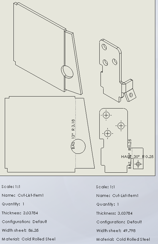
- Projection file: The projection file allows you to assign layers to features during DXF/DWG export. You can create this file in SOLIDWORKS and import it into SheetMetalManufacturing for exports.

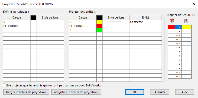
- " Force 3D Activation ": With certain files, the generated views may be incorrect because they display the entire file rather than the individual bodies. This option uses a different, more time-consuming method but avoids the problem.
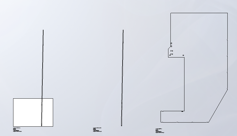
Before and After:
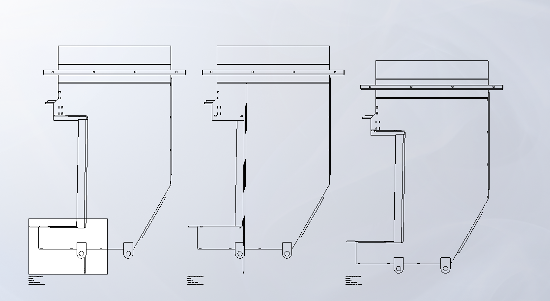
- 2D Grouping:
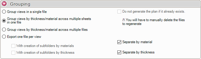
If multiple sheet metal bodies are being processed, a view will be created for each conversion; in this case, you must specify whether sheet metal bodies of the same thickness should be grouped together:
- One drawing per thickness. Multiple files if there are multiple thicknesses.
- In a single drawing, but separated into multiple sheets based on material or thickness.
- In multiple drawings, but with views grouped by thickness or material.
- Or export a drawing by view, creating subfolders by material or thickness.
There is an option to skip generating the drawing if it already exists.
- 3D Grouping:
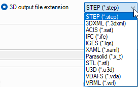
You can export the solids in various 3D formats:
There are two options for generating one or more export files:
