Entering project elements
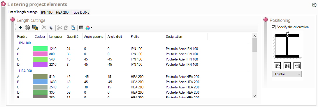
This frame lets you define a list of profiles and enter all the elements to be cut. To access this window, use the icon  .
.
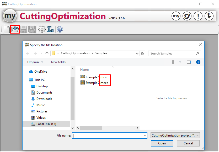
You can also open a previously saved project by clicking on the  .
.
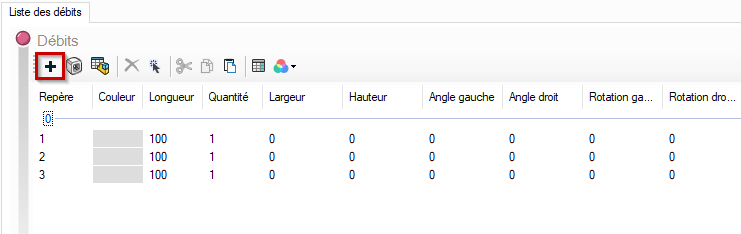
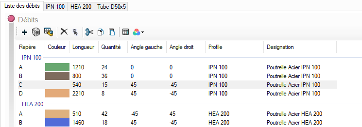
- Add items :
- Add items manually :
Click on the  allows you to add items to the debit list.
Once the element has been added, double-click in the '' column.Profile'' to display the drop-down menu with the list of profile bases.
If you have several profile databases (.csv files), they will all appear in the drop-down menu.
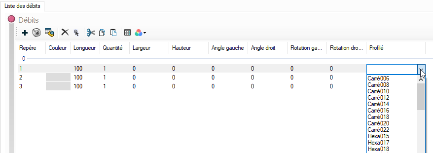
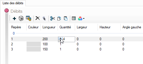
Select the desired profile and change the ''.Lengthand theQuantitydouble-click on the corresponding columns.
- Adding elements from a weldment table :
The '' iconImport SW table'' allows you to create a project by retrieving elements from a mechanized welding table SOLIDWORKS.
See paragraph ''Creating a project from a table''.
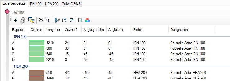
- Add a color
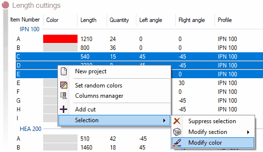
It is also possible to apply a color to the marker:
- Double-click on the corresponding cell.
- Select several markers, then "Right-click", "Select" and then "Change color".
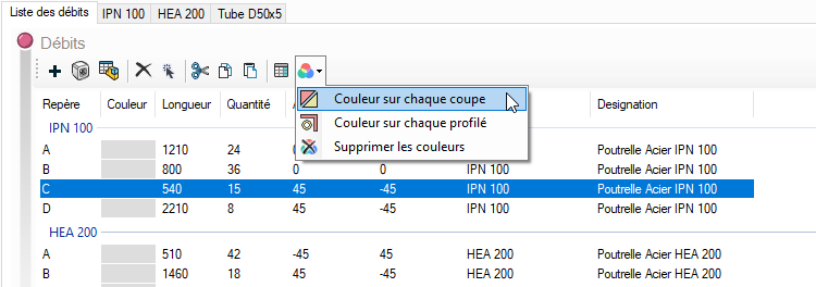
It is also possible to randomly assign a color according to :
- the cup
↓
- profile
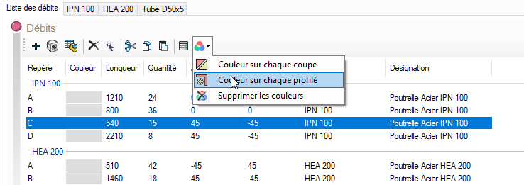
↓
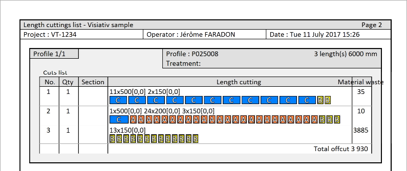
This color will then appear in the report for greater visibility of the cuts.
Click again on the '' iconAdd a flow to the project'' to add a new element.
Columns defined in CuttingOptimizationsee paragraph ''Column management''
- Adding elements from a weldment table :
The '' iconImport SW table'' allows you to create a project by retrieving elements from a mechanized welding table SOLIDWORKS.
See paragraph ''Creating a project from a table''.
- Angle dimensioning :
It is possible to define a cutting angle for each profile. The value will depend on the option selected in the '' section.Machine & bar''.
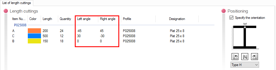
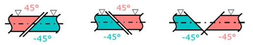
The '' cutsLeft angle'' and ''Right angleare defined according to the following rule :
- Positioning :
When using angled cuts, the profile orientation can be specified.
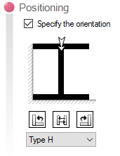
To specify an orientation, select the profile and check the '' option.Specify orientation''.
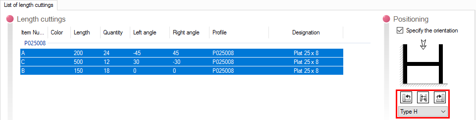
- The drop-down menu  to select the profile type.
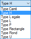
These images are located in a subfolder in the installation directory, and you can add more if you don't like the list.
- The icons  rotate the selected profile.
- The design  represents the blade.
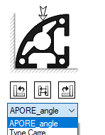
Create a profile orientation image.
You can create your own profile images.
For example, we're going to create an icon for an APORE_angle profile.
To do this, follow these steps.

- Shape in an application (e.g. SOLIDWORKS).
- Colour the side to be shown in black.
- Make the capture as square as possible, close to 100 pixels square. However, it is necessary to leave a white band around the black object. Here, we've marked the edges of the image with a rectangle that must not be present in your image. In other words, the object is 80x80 pixels, leaving 10 pixels all around.
- In an image editor, if necessary, resize to 100x100 pixels.
- Save image in PNG format in :
C:\Users\<Name>Documents\myCADtools\CuttingOptimization\fr\Sections --> for the French version
C:\Users\<Name>\Documents\myCADtools\CuttingOptimization\en\Sections --> for the English version
This new profile will be available in the "Profile type" drop-down menu.