Presentation
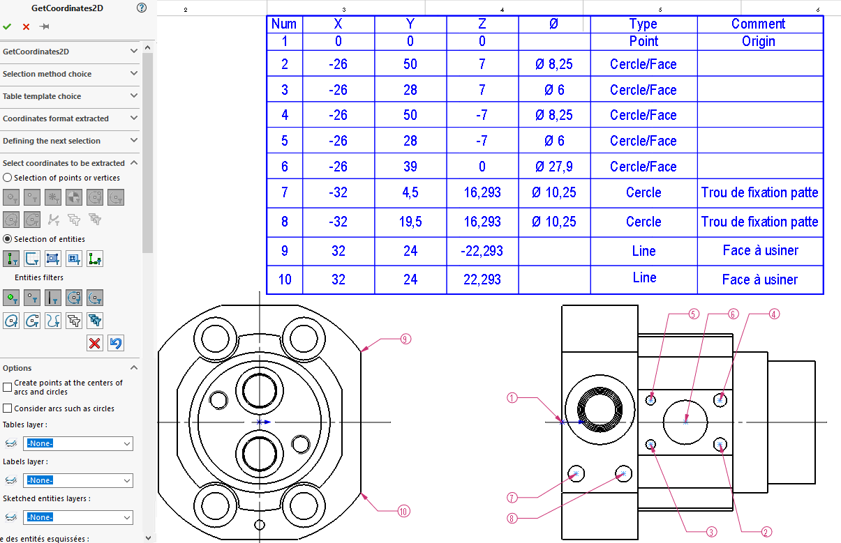
The end result is to have the selected points automatically annotated on the drawing and listed in a scoring table.
Selection can be refined by activating filters.
Has a function GetCoordinates2D corresponds to one and only one coordinate table, but it is possible to create several coordinate tables, i.e. several MacroFeatures by running the tool several times.
Use in the context of drawing a part or assembly.
- First of all, you need to select the selection method. DTwo coordinate extraction methods are available to the user:
- Method "3D mode"This is where you extract X, Y and Z data in the 3D model frame. Selection can be made from several views.
- Method "Projected mode"extract X, Y data in the XY frame of a view and of one. All selected entities are projected onto a plane parallel to the sheet (Z is not taken into account).
- Then use a formatted table. If no table exists, a template must be created. Several templates can be created, depending on the information you want to appear in the final table.
- The next step is to define the coordinate format and, in particular, the choice of reference frame (coordinate origin).
- If other than "1", set the starting numbering, then the next selection numbering and, if applicable, the associated comment.
- Choice of selections coordinates to be extracted. Selection filters can be activated.
- Finally, it is possible to adjust certain options such as layer assignment of information generated by GetCoordinates2D.
- Has a function GetCoordinates2D corresponds to one and only one coordinate table. It is possible to create several coordinate tables, i.e. several MacroFeatures by lacing the tool several times. These functions are also available in the FeatureManager.